Pistons in air compressors, steam engines, and vacuum pumps often utilize a pressure feed lubrication system using lube oil pumps. Failure of this lubrication system can have devastating effects on the piston’s operation, which is why proper lubrication in a piston assembly is an essential consideration when designing traditional pistons.
The Dirty Alternative
In order to avoid system failures, some piston designs take advantage of splash lubrication. Instead of feeding oil up to the piston by means of a pump, splash lubrication relies on oil splashed up to the piston from an oil pan in the bottom of the crankcase. Although splash lubrication is a simple solution that is more easily implemented than a forced lubrication system, it has its flaws. Under-lubrication, over-lubrication, and oil contamination are just a few possible failure modes of a splash lubricated piston system.
The only foolproof way to eliminate lube system concerns is to get rid of your lubrication system altogether.
Lube-Free Meets Modern Needs
To avoid the potential headache of a faulty lube system, and to accommodate for applications where oil and grease lubricants would contaminate products (like many applications in the food and pharma industries), many engineers now turn to piston ring designs that are completely lubrication-free. On top of eliminating the potential failure modes associated with a typical lubrication system, lubrication-free piston assemblies allow designers to handle compressed gases without picking up oil or grease during compression.
This is crucial to designing systems like air compressors that need to produce pressurized air that is completely free of suspended oils. By taking advantage of modern self-lubricating materials like carbon graphite, engine designers can eliminate lubrication systems from their designs altogether and open themselves up to a new world of potential applications.
How to Make Self-Lubricating Designs Work for Your Application
Although going completely lubrication-free would ideally benefit all piston ring designs, not all applications lend themselves to self-lubricating piston rings.
Carbon graphite’s relatively low impact resistance and susceptibility to cracking limits where it can be safely used; only those applications where there is a relatively low pressure differential and piston speed can take advantage of carbon graphite piston rings. That’s why you typically don’t see carbon graphite piston rings in your car engine. However, carbon graphite is durable enough to be used in lower pressure applications, such as refrigerant pumps or dry running gas compressors.
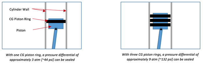
In higher pressure applications, designers can compensate for limited sealing capabilities by increasing the number of piston rings in their design, but they are often constrained by the envelope used to house the piston rings.
The approximate number of carbon graphite piston rings required in a specific application is related to the pressure differential (in atmospheres) through the following formula:
# of rings ≈ 0.3 · Δp
It is important to note that this formula is an approximation. We always recommend that piston ring designers test new designs before implementation.
Combat Wear and Tear: Ring Design Guidelines for Dry Running Applications
Since most applications utilizing carbon graphite piston rings are dry running, piston ring wear rates are often a point of concern in the design phase. To combat the conditions that cause excessive wear in dry running applications, it is important that the ring design takes certain guidelines into account:
- Fine cylinder wall surface finish, with a roughness of 12 Ra or better.
- Piston speeds should not exceed 10 ft/s.
- Carbon graphite piston rings should have a larger cross section than metal piston rings to compensate for the lower strength material.
- Use an external pressure element (i.e. a leaf spring) to provide outward pressure of 1-3 psi on the piston ring ensuring a proper seal against the cylinder wall. Too high pressures increase the wear rate without additional sealing effect.
Special Considerations: Backing Springs and Ring Splits
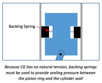 Backing springs are typically not a concern in traditional cast iron piston rings, but must be addressed when dealing with carbon graphite. Since carbon graphite has no natural tension, the sealing pressure between the piston ring and the cylinder wall must be provided by an external source. This source is usually some type of spring.
Common spring options include:
- leaf springs
- corrugated spring bands
- cast iron tension rings
- spiral compression rings
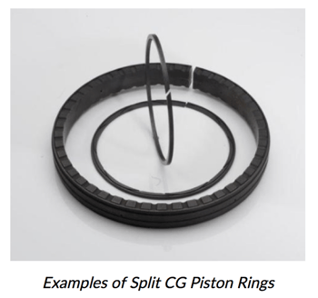
Carbon graphite piston rings must have at least one split along the circumference—a solid ring will not be able to supply sufficient sealing pressure around the circumference of the ring. Although a single diagonal split in the piston ring is sufficient in many designs, piston ring designers can also utilize multiple splits, meaning the piston ring is essentially acting as a segmented seal ring.
In longer piston designs where a single split ring can’t easily slide into place, segmented piston rings offer more ease-of-installation. In these cases, the segments can simply be placed around the piston and held in place by the cylinder wall.
Piston ring designers are constantly looking for new ways to improve old designs to avoid the issues and extra resources and maintenance efforts they cause. The move towards self-lubricating materials has opened new possibilities and improved the reliability of many existing piston designs. Advances in carbon graphite technology are constantly pushing the boundaries of self-lubricating piston ring applications – as more material grades are being developed, even more can be done with this amazing technology.
Get in touch with a Metcar engineer today to see which grade is right for your application.